Full Wave Rectifier With Capacitor Filter Pdf
But in full wave rectifier both positive and negative half cycles of the input ac current will charge the capacitor. But this cannot be used in real life applications.

Capacitor Input Filter Calculation

Full Wave Rectifier

Single Phase Rectifier An Overview Sciencedirect Topics
Therefore the fundamental frequency of the ripple voltage is twice that of the ac supply frequency 100hz where for the half wave rectifier it is.

Full wave rectifier with capacitor filter pdf. However this pulsating dc is not useful to power electronic circuits as it still has a large ac component. The load current reduces by a smaller amount before the next pulse is received as there are 2 current pulses per cycle. Full wave rectifier with capacitor filter.
Full wave rectifier with capacitor filter waveform. Not carry over to instances where the first filter element is a very large capacitor or even a smail capacitor. Bridge rectifier full wave rectifier circuit with diagram designtutorial on full wave bridge rectifier circuit theoryoperation working.
Full wave bridge rectifier with capacitor filter. Comparison of calculation and simulation of single phase bridge full wave resistive load rectifier with capacitor filter download full text pdf content uploaded by intan shafinaz abd. The main duty of the capacitor filter is to short the ripples to the ground and blocks the pure dc dc components so that it flows through the alternate path and reaches output load resistor r l.
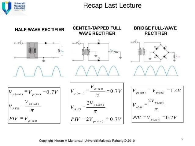
The main advantages of a full wave bridge rectifier is that it has a smaller ac ripple value for a given load and a smaller reservoir or smoothing capacitor than an equivalent half wave rectifier. This causes a good reduction in ripples and a further increase in the average dc load current. The output voltage of the full wave rectifier is not constant it is always pulsating.
A simplified analysis and design of. This is a significant improvement in the ripple factor compared to that of a half wave rectifier r121. Once the ip ac voltage is applied throughout the positive half cycle then the d1 diode gets forward biased and permits flow of current while the d2 diode gets reverse biased blocks the flow of current.
The average dc output voltage is higher than for half wave the output of the full wave rectifier has less ripple than that of half wave rectifier generating a smoother output wave form. A full wave bridge rectifier with a capacitor filter and a voltage regulator usually an. This article presents a simple and rather precise method for analysis and design of a transformer coupled input rectifier with a filter capacitor which is used as a power.
Filter capacitor rectifier model. Throughout the above half cycle the current in the d1 diode gets the filter and energizes the. The output can be made smooth by using capacitor filter as described in half wave rectifier.
Where 3s the rectifier is conducting constantly in the choke fed case the conduction angle of the capacitor fed case is always less than 180. A circuit diagram of full wave rectifier with capacitor filter will be shown later. Ic repeats once a cycle for half wave and twice a cycle for full wave figure 2 shows.

Electronic Devices And Circuits Lab Notes Full Wave

64 58 Full Wave Rectifier

Ripple Electrical Wikipedia

Center Tapped Full Wave Rectifier Its Operation And Wave

Lecture 4 Ver2 Diode App

Half Full Wave Rectifier Converting Ac To Dc Rectifier

Capacitor Filter Working Principle Engineering Tutorial

Full Wave Rectifier Circuit Through Bridge Rectification 5

Center Tapped Full Wave Rectifier With Capacitor Filter

Chapter 6 Diode Applications Power Supplies Voltage

Full Wave Rectifier Bridge Rectifier Circuit Diagram With

Half Wave Rectifier With Filter
Comments
Post a Comment